Why TOPCon Four-Cut Modules Need Two-Part Junction Boxes: A Look at PV Junction Box Evolution
Table of Contents
Product Introduction
Junction box designs keep changing, but it's never just a cosmetic tweak to the plastic shell. Every structural change is tuned to match the module's internal circuit layout and its shifting electrical parameters. It's a hard requirement that comes along with each step of PV technology. Here we'll walk through the history of the PV junction box, and dig into why TOPCon four-cut modules end up using a two-part junction box.
Technical Parameters
One-Piece Junction Box: The Early Full-Cell Module Match
2016 was a turning point for module structure. Before 2016, the market ran mostly on full-cell modules, with the internal circuit built as one complete string. Back then module working current was on the low side and voltage was moderate, so the electrical conditions were pretty mild across the board. The industry commonly paired these with a one-piece single junction box, with all three bypass diodes tucked inside the same shell.
That setup fit the production conditions of the day: uniform part specs, dead-simple structure, low skill bar for manual assembly, and high line throughput. Full-cell modules handled wiring with side isolation strips plus trapezoidal busbars. Easy to build, low overall cost. It was the most cost-effective landing plan for the full-cell technology route.
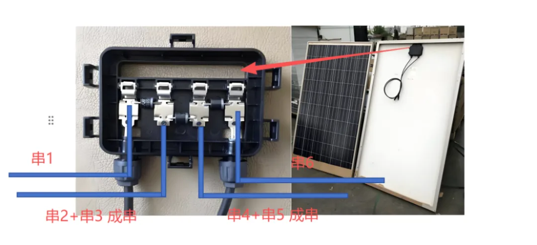
Full-cell module junction box
| Item | Detail |
|---|---|
| Era | Before 2016 |
| Module type | Full-cell modules |
| Circuit layout | One complete single string |
| Junction box | One-piece single box |
| Diode count | 3 bypass diodes in one shell |
| Working current / voltage | Low current, moderate voltage |
Technical Advantages
Three-Part Junction Box: The Current Half-Cut Module Match
After 2016 half-cut cells spread fast, and the three-part junction box became the common industry config. Half-cut modules use an upper-lower symmetrical structure, where the upper cell string and the lower cell string are connected in parallel. Once merged, the overall voltage stays the same and the current gets combined. That change in circuit architecture made the three-part design a must-have. Its edge comes down to four points:
As module power climbed, working current and voltage rose together. The three-part layout puts one diode in each shell, so heat sources are spread out. Better heat dissipation, and it dodges the old single-box problem of heat piling up in one spot and cooking the components over time.
The three boxes sit spread across the backsheet, splitting up and diluting the shaded area. That fits bifacial modules perfectly, since they rely on the backsheet catching reflected light to generate power. A centralized single box just can't do this.
Circuit zones map one-to-one with junction boxes, so busbar routing gets a lot shorter. Line resistance drops, the module's fill factor goes up, and whole-module output power improves.
Wiring uses less material. A vertically mounted module only needs about 300 mm of short wire to finish the connection. In mass production that trims cable cost, and it plays nicer with fully automated lines.
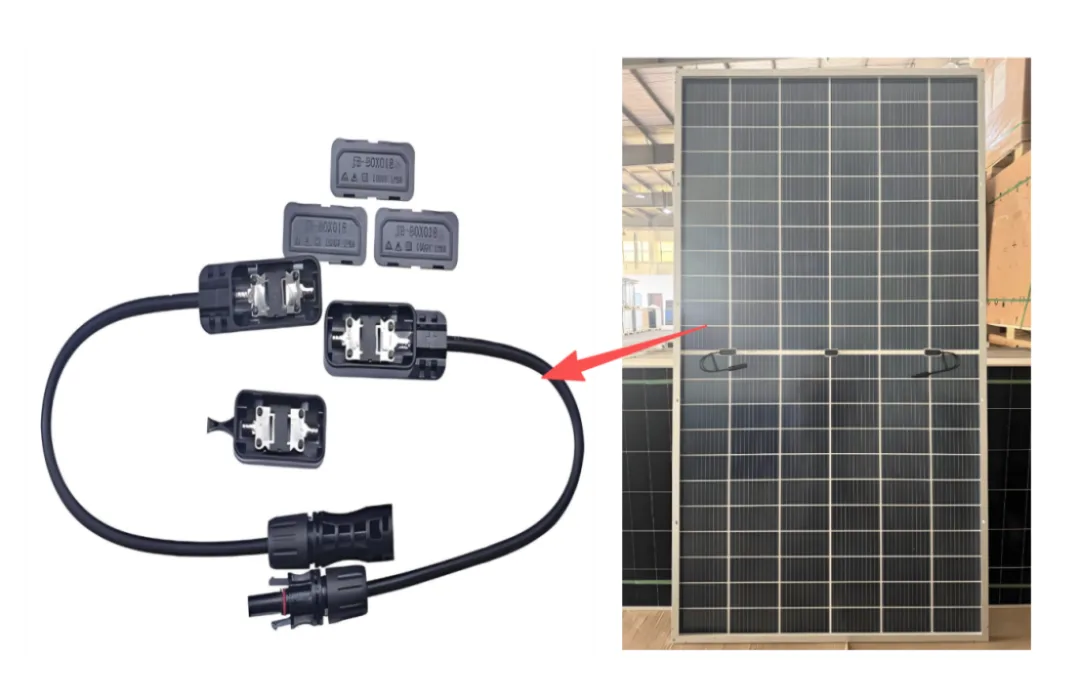
Half-cut module junction box
Product Application
Two-Part Junction Box: The High-Efficiency TOPCon Four-Cut Module Match
With TOPCon high-efficiency cells hitting mass production, four-cut modules moved into the mainstream, the circuit logic got rebuilt again, and the two-part junction box became the standard match.
The industry follows the half-cut rule of "cut in half, two paths in parallel." Once the cell is split into four equal parts, it has to be made into four parallel paths to hold the current range steady. The module still keeps the upper-lower symmetrical layout: cells on one side pair up two-by-two into an independent unit, and three of these parallel units are then connected in series, keeping the voltage and current ranges stable.
This circuit layout needs two cell units set with reversed positive-negative polarity, so the two matching bypass loops each need one diode. Since those two points sit very close together, the two diodes get integrated into the same box body. The whole circuit splits into two big protection zones, and ends up paired with two junction boxes. The box holding the double diode is longer in size, and that's the underlying circuit reason four-cut modules go with two-part junction boxes. On top of that, the extra auxiliary wire added by the reverse routing has to be paired with a transparent PET insulation layer for proper isolation, keeping things electrically safe.
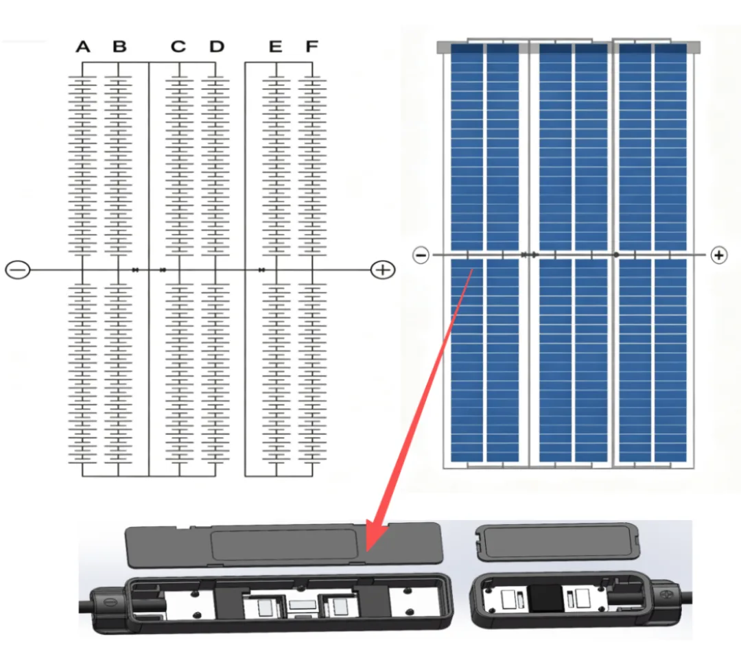
Four-cut module junction box
At bottom, the number of junction box shells is just the visible outer form. From full-cell single box, to half-cut three boxes, to four-cut two boxes, the total of three diodes never changed. Each diode still covers two cell strings for bypass protection, and the underlying logic of zoned protection stayed put the whole way through. Box count moves with the circuit, the circuit follows the cutting technology, and the whole set of parts always serves module electrical safety and output efficiency.
Ooitech's View
The two-part junction box on TOPCon four-cut modules isn't a gimmick, it's forced by the reverse-polarity, four-parallel circuit that four-cut layouts run. If you're building a line, this matters on the layup and bussing side, since the box position, the reverse routing and that PET insulation layer all have to be handled right or you get EL defects and safety headaches. We've built module lines for half-cut, MBB and TOPCon setups, and the junction box step is one that quietly decides your yield. Worth watching a few real factory line runs on the Ooitech YouTube channel www.youtube.com/ooitech if you want to see how the bussing and box placement actually go together.